Cool But Daddy I Love Him Shirt Harry Ideas

Cool But Daddy I Love Him Shirt Harry Ideas . Our prints are not vinyl. No products in the cart. but daddy i love him shirt Classic I love h...

Wednesday, August 31, 2022

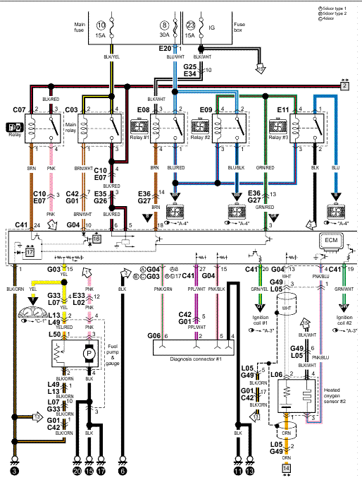
Central Door Lock Wiring Diagram

Kia wiring diagrams free download for such models, as: Hyundai coupe central locking wiring reverse door system installing how a car center lock vehicle keyless entry diagram chinese do i install.


Wiring Diagram Central Locking Kit

10th august 2012, 09:30 am #2.
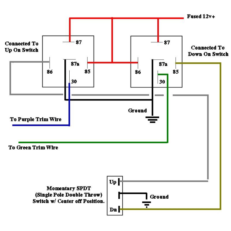
Central door lock wiring diagram. When you make use of your finger or the actual circuit with your eyes, it is easy to mistrace the circuit. Be sure to mount the module in a dry place (under the dash). The switch changes polarity on a single wire that may rest at power or ground depending on the state of the door locks.

I had a similar problem on the front doors.after taking it to a garage for a quote £ 180 i read into it and there are micro swithches in the locks so with a gentle tap with the hand the door unlocks. There is also a control unit that enables the whole system to function. Such a kit essentially comprises a number of motors.

For a few pounds, you can buy a kit from any automotive accessory shop that will allow your car to be fitted with a central locking door system. For connection to rhino central locking kit configure wiring as above & refer to diagram below: If the year of your vehicle is listed as having two or more types of door lock systems, you must test for

How central door lock actuators and door lock relays work in detail.www.lesscosales.comwww.lesscoelectronics.com here are some of the. 1990 volvo 760td engine fuse box diagram 1990 volvo 760td engine fuse box. Remove door panels carefully 2.

This wiring information is being provided free of charge on an as is basis, without any representation or warranty. Found mostly on mercedes benz vehicles, the movement of the door lock actuators is controlled by a central vacuum pump. Hope this helps it saved me the money.

Run all the wires to the location of the door lock module. Connect the separate black wire to a. It is your responsibility to verify any.

The driver's door actuator is the master actuator. Central locking system installation manual actuators installation 1. To help determine your door lock type, refer to the door lock types by manufacturer chart (see below) or in most cases we provide you with the central lock wiring colour's diagram for your car (normally a separat sheet is enclosed).

Central locking wiring diagram by bobson6 » tue nov 02, 2010 1:00 pm the wires go from the passenger foot well, up the front pillar (next to windscreen, the plastic panel comes off easily) then along the roof edge to just past the sliding door, then down the edge of the door to the lock. I show you how to wire them up and the reasons why.how to wire door lock and power window switches tutorial. Car central lock by nfc tech:

Make sure that actuator will not block other moving parts inside of door (screen and its mechanism). The central locking wiring diagram manual application provides many reference images about the best door locking wiring diagram. Electric door lock wiring diagram and central locking help:

Connect the 5 wires from the actuator to the wire harness in accordance with the same color. After the wiring diagram for central locking if anyone has it? Trying to hook up an alarm to operate it all and there be 5 wires on the drivers actuator!

Focus central locking module wiring diagram ford focus ford make sure that actuator will not block other moving parts inside of door screen and its mechanism. Central door lock system wiring diagram. Car central lock wiring diagram and how to wire door lock relays for aftermarket actuators.

You can duplicate this with at least a 2 second pulse. The master drive unit is identified by having two extra wires connected to it. Also make sure that actuator is moving parallel to door lock.

These are the feed and earth return for the entire door lock system.


Car Central Lock Wiring Diagram


wiring diagram for aftermarket door locks Car Audio


Door Lock Actuator Wiring Diagram Mes 5 Wire Great Central


Nippon Central Locking Wiring Diagram


Door Lock Actuator Wiring Diagram Wellread Me And Power


Home Entrance Door Entrance Door Lock


Central Door Lock Wiring Diagram Wiring Diagram


Wiring Diagram For Central Locking Actuator


Does anyone have a wiring diagram for the central locking


Youan E30 Central Locking Wiring Diagram


Central Locking Wiring Diagram Manual


Wiring Diagram Central Lock Home Wiring Diagram


Wiring Diagram For Central Locking Kit


Mk2 Golf Central Locking Wiring Diagram Wiring Diagram


Mercedes Vito Central Locking Wiring Diagram


central lock wiring diagram universal Wiring Diagram


Central Door Lock Wiring Diagram Wiring Diagram


Door Lock Actuator Wiring Diagram Universal Power Door


Car Central Lock Wiring Diagram

Tuesday, August 30, 2022

Exit Wand Wiring Diagram

Usually ships in 24 to 48 hours product code: Gto exit wand instructions 12.28.11 3 4.


Exit Sign Installation! YouTube

Battery) • connect the red wire to the (+) positive side of power

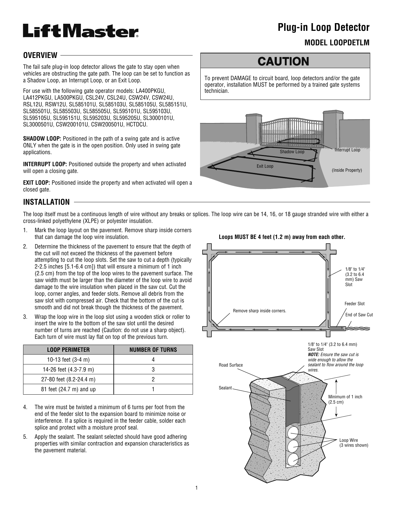
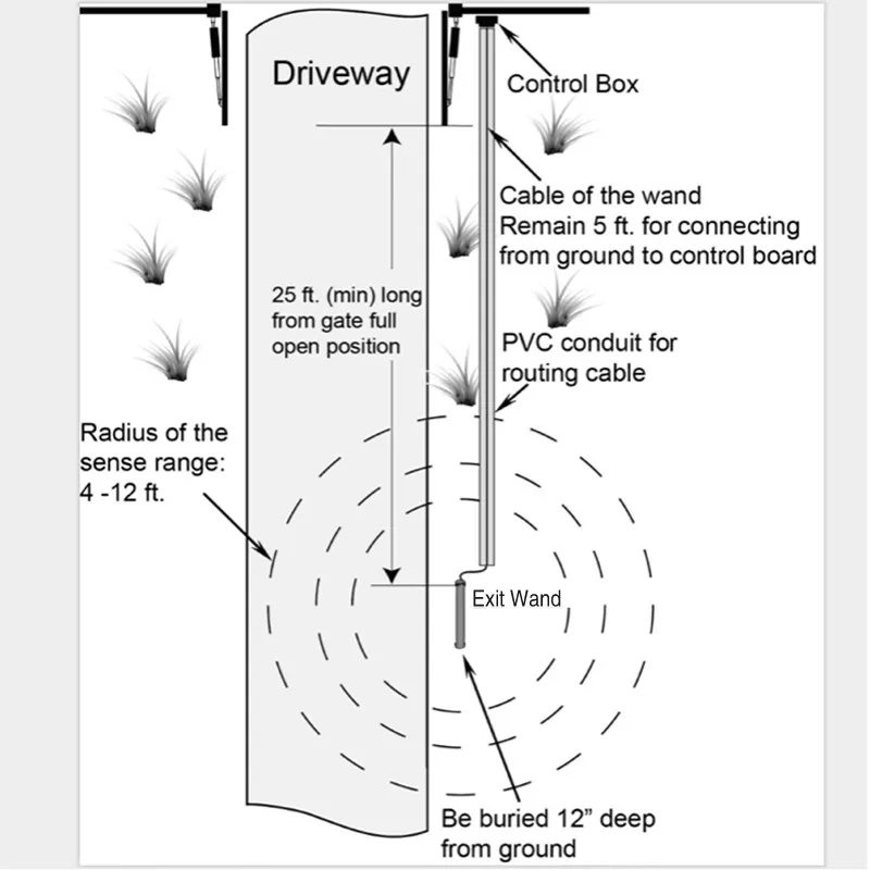
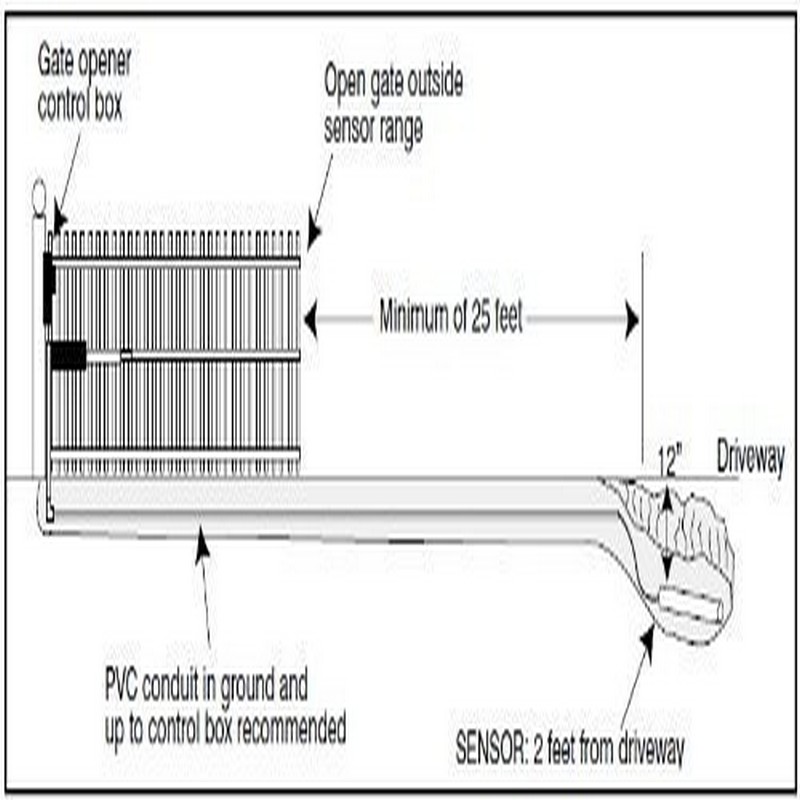
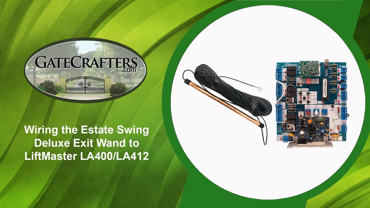
Exit wand wiring diagram. Connect the power input wires from the exit wand sensor (if not already connected to a The deluxe model includes 100 feet of lead wire to support an. An easy way to explain how exit wands work is to picture a boat traveling through the water.

10) make sure that the magnetic field of the exit wand is clear of any tools. This video is about wiring es deluxe exit want to apollo Sometime a bit slow to trigger the contacts to open as well.

Pretty sure the sensitivity module is worthless. Connect the black to the terminal labeled common, and the blue wire to terminal in step 3 to open gate. It's a sturdy feeling piece, but doesn't always pick up the vehicle upon exit.

Wiring the exit wand note: Connect the power input wires to power source. Cartell, makers of smart driveway alarm and free exit systems.

Easy diy (do it yourself) installation to. Connect the black to the terminal labeled common, and the blue wire to terminal in step 3 to open gate. Only disconnect the operator when the control box power switch is.

Read and follow all instructions. Ii mm371w / mm372w installation instructions mm371w / mm372w installation instructions iii caution the gate will move freely and uncontrolled when the gate operator is removed from the gate. Club car precedent wiring diagram 48 volt;

Manual how to buy features specifications faq documents warranty opens gate automatically when leaving property. Aleko® lm157 exit sensor underground automatic gate opener exit wand: This item is really on the cheaper side of exit wands.

Kawasaki mule 3010 wiring diagram; Liftmaster la412u wiring diagram exit wand diagram; The wired driveway vehicle sensor allows a vehicle to drive past the sensor's 12 ft.

Connect the black to the terminal labeled common, and the blue wire to terminal in step 3 to open gate.see wiring diagrams to the right for guidance on wiring the sensor to your gate opener's control board. If your usautomatic product also referred to as the product does not work properly due to a defect in materials or workmanship. Maf wiring diagram e39 m5 bmw site;

To wire or connect the exit wand to a mighty mule /, pro /, 1 ) locate the range adjustment board for the gate opening sensor or exit wand. Battery) • connect the red wire to the (+). This wiring is for connecting to richmond gate automation kits.

Gto exit wand instructions 09.18.14 3 4. Free exit sensor (100 feet) the driveway free exit sensor is a magnetic device that installs below ground beside the drive to open your gate automatically. Insert the adapter board into the loop detector socket of the control board.

If the unit is too sensitive the range adjustment board can be wired in line with the ground lead which will decrease the sensitivity of the exit sensors detection. 2 safety » safety installation information 1. This video is about driveway gate exit wands and exit loops and how they work.gatecrafters.com/?utm_source=youtube&utm_medium=contentlink&utm_campaign=drivew.

Gate opener exit wands are also known as magnetometers, which sense changes in the earth¡¯s magnetic field. Keep the exit wand and the cable uncovered until all functions of the wand have been tested and the gate is successfully opening and closing automatically. Wiring diagram of the wand to the rk 990&rk1200&ck1200 sliding gate opener

Cub cadet ltx 1045 drive belt diagram; Connect the power input wires to power source. One accessory that is only found with the estate swing 75 foot standard model exit wand, is a range adjustment board.

Aleko® lm157 exit sensor underground automatic gate opener exit wand : To wire or connect the exit wand to a mighty mule pro 1 locate the range adjustment board for the gate opening sensor or exit wand. As the boat travels, it creates waves.

The exit wand is comprised of three elements: Aleko gate opener wiring diagram : I got this to try out and have had multiple call outs for it not working.


Liftmaster La412u Wiring Diagram Exit Wand Diagram


Apollo Wiring Diagram Fuse & Wiring Diagram


Cartel Exit Wand 100 Ft lead 3 wire for use with


How To Connect Your CP31003W Exit Wand To Nice Apollo


Wiring ES Deluxe Exit Wand to Apollo 635/636 & 835/836


Gate Opener Exit Loop Gate Opener


Car Sensor Exit Wand For Gate Opener Ew01 Buy Exit Wand


Pin by Amy Zimmerman on NCIDQ Fire protection system


Gate Opener Exit Loop Gate Opener


Loop Detector Wiring Diagram 6


Gate Opener Exit Loop Gate Opener


Gate Opener Exit Loop Gate Opener


Jayco Esc Wiring Diagram How To Connect Your CP31003W


Liftmaster La412u Wiring Diagram Exit Wand Diagram


Liftmaster La412u Wiring Diagram Exit Wand Diagram


WIRING DIAGRAM, DISCONNECT power AC or solar and battery


Swing Gate Wiring Diagram Complete Wiring Schemas


Liftmaster La412u Wiring Diagram Exit Wand Diagram


Gate Opener Exit Loop Gate Opener

Monday, August 29, 2022

The Best Angel Care Home Health Russell Ks References

The Best Angel Care Home Health Russell Ks References. See other home health services, nurses, medical assistants & technicians in russell, ks. Wichita, ks angels care home health.

UConn Women's Basketball Crystal Dangerfield, Evina Westbrook Undergo
UConn Women's Basketball Crystal Dangerfield, Evina Westbrook Undergo from www.chatsports.com

Russell, ks angels care home health. This agency has been certified to participate in medicare programs since february 19, 1988 and given a rating of 3.0 stars. 5375 southwest 7th street, topeka, ks, usa;

Name Angels Care Home Health Address 802 North Maple.


802 n maple st, russell, ks, usa; High quality 0 good service 0. Angels home health care provides home health care services for senior patients in russell, ks.

Angels Care Home Health Is A Proprietary, Medicare Certified, Home Health Care Agency Located In Russell, Ks.


Angels care home health is located at 802 n maple st, russell, ks 67665. Angels home health care provides home health care services for senior patients in winfield, ks. Angels care home health jobs near russell, ks.

Angels Home Health Care Provides Home Health Care Services For Senior Patients In Wakeeney, Ks.


Research salary, company info, career paths, and top skills for home health aide Use our convenient locator tool to find a russell, ks angels care location near you. See other home health services, nurses, medical assistants & technicians in russell, ks.

A Rating Of 3 Stars Would Indicate This Agency Has An Average Rating Compared To Other Agencies.


Angels care home health 2301 highway 1187 suite 203 mansfield, tx zip 76063 phone: Full health, dental & vision benefits (available 1st month) we offer comprehensive & competitive medical and dental benefits. Please click below to find more providers like this.

Angels Care Home Health Is Now Hiring A Registered Nurse To Join Our Growing Team In Russel, Ks.


Apply today to learn more! Come visit our nearby location at 802 north maple russell ks ~zip~. Angels care physician's administer medical services to patients in private residences, retirement communities, assisted living facilities or wherever they.