
Usually ships in 24 to 48 hours product code: Gto exit wand instructions 12.28.11 3 4.

Exit Sign Installation! YouTube
Battery) • connect the red wire to the (+) positive side of power
Exit wand wiring diagram. Connect the power input wires from the exit wand sensor (if not already connected to a The deluxe model includes 100 feet of lead wire to support an. An easy way to explain how exit wands work is to picture a boat traveling through the water.
10) make sure that the magnetic field of the exit wand is clear of any tools. This video is about wiring es deluxe exit want to apollo Sometime a bit slow to trigger the contacts to open as well.
Pretty sure the sensitivity module is worthless. Connect the black to the terminal labeled common, and the blue wire to terminal in step 3 to open gate. It's a sturdy feeling piece, but doesn't always pick up the vehicle upon exit.
Wiring the exit wand note: Connect the power input wires to power source. Cartell, makers of smart driveway alarm and free exit systems.
Easy diy (do it yourself) installation to. Connect the black to the terminal labeled common, and the blue wire to terminal in step 3 to open gate. Only disconnect the operator when the control box power switch is.
Read and follow all instructions. Ii mm371w / mm372w installation instructions mm371w / mm372w installation instructions iii caution the gate will move freely and uncontrolled when the gate operator is removed from the gate. Club car precedent wiring diagram 48 volt;
Manual how to buy features specifications faq documents warranty opens gate automatically when leaving property. Aleko® lm157 exit sensor underground automatic gate opener exit wand: This item is really on the cheaper side of exit wands.
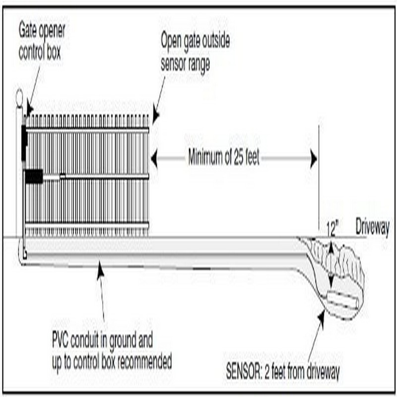
Kawasaki mule 3010 wiring diagram; Liftmaster la412u wiring diagram exit wand diagram; The wired driveway vehicle sensor allows a vehicle to drive past the sensor's 12 ft.
Connect the black to the terminal labeled common, and the blue wire to terminal in step 3 to open gate.see wiring diagrams to the right for guidance on wiring the sensor to your gate opener's control board. If your usautomatic product also referred to as the product does not work properly due to a defect in materials or workmanship. Maf wiring diagram e39 m5 bmw site;
To wire or connect the exit wand to a mighty mule /, pro /, 1 ) locate the range adjustment board for the gate opening sensor or exit wand. Battery) • connect the red wire to the (+). This wiring is for connecting to richmond gate automation kits.
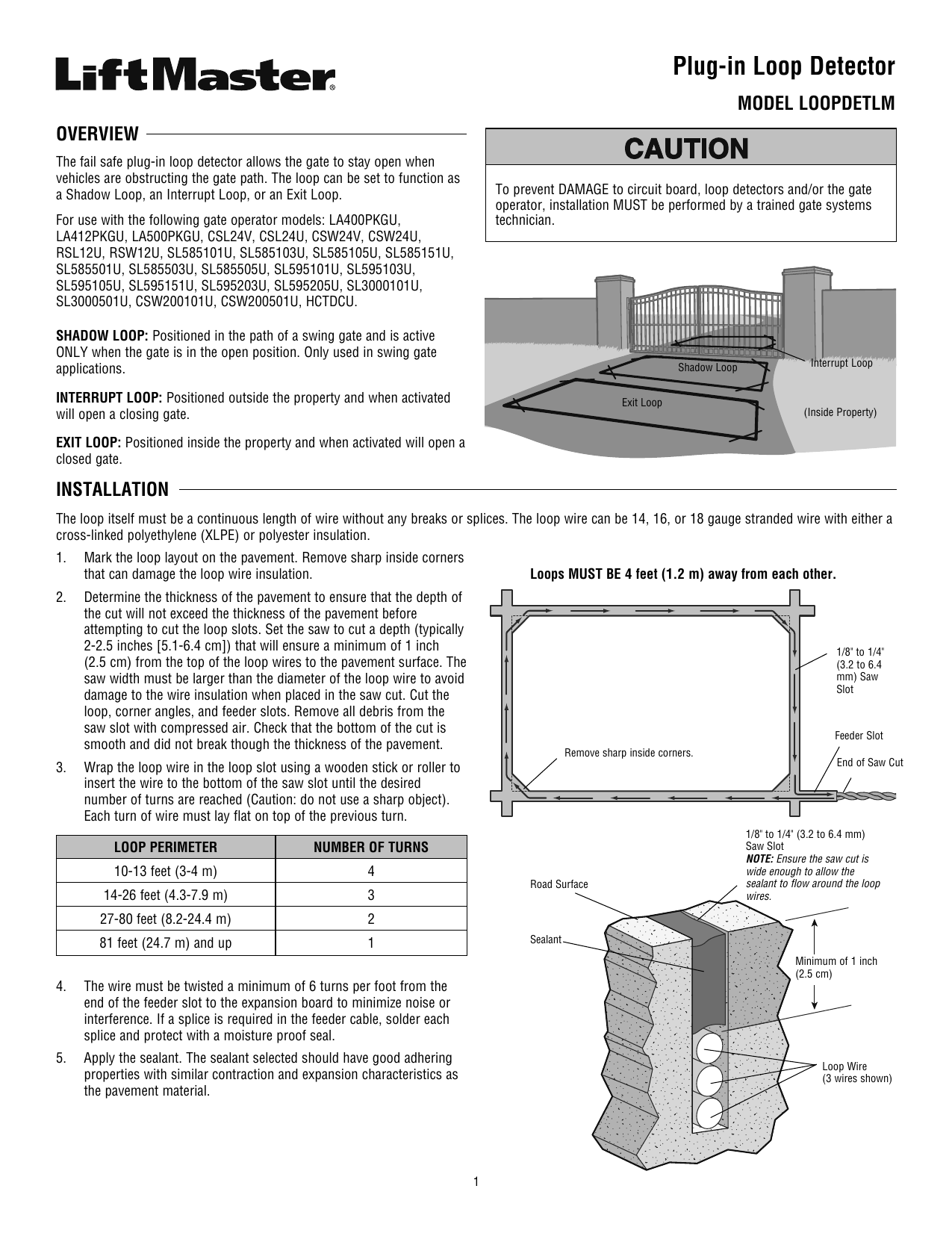
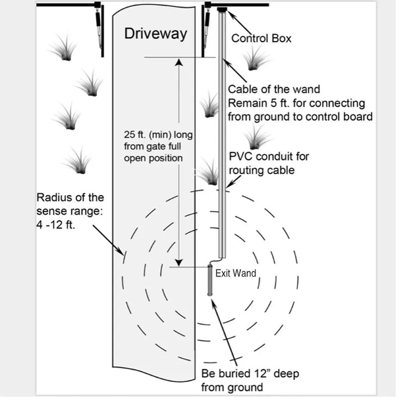
Gto exit wand instructions 09.18.14 3 4. Free exit sensor (100 feet) the driveway free exit sensor is a magnetic device that installs below ground beside the drive to open your gate automatically. Insert the adapter board into the loop detector socket of the control board.
If the unit is too sensitive the range adjustment board can be wired in line with the ground lead which will decrease the sensitivity of the exit sensors detection. 2 safety » safety installation information 1. This video is about driveway gate exit wands and exit loops and how they work.gatecrafters.com/?utm_source=youtube&utm_medium=contentlink&utm_campaign=drivew.
Gate opener exit wands are also known as magnetometers, which sense changes in the earth¡¯s magnetic field. Keep the exit wand and the cable uncovered until all functions of the wand have been tested and the gate is successfully opening and closing automatically. Wiring diagram of the wand to the rk 990&rk1200&ck1200 sliding gate opener
Cub cadet ltx 1045 drive belt diagram; Connect the power input wires to power source. One accessory that is only found with the estate swing 75 foot standard model exit wand, is a range adjustment board.
Aleko® lm157 exit sensor underground automatic gate opener exit wand : To wire or connect the exit wand to a mighty mule pro 1 locate the range adjustment board for the gate opening sensor or exit wand. As the boat travels, it creates waves.
The exit wand is comprised of three elements: Aleko gate opener wiring diagram : I got this to try out and have had multiple call outs for it not working.
Liftmaster La412u Wiring Diagram Exit Wand Diagram

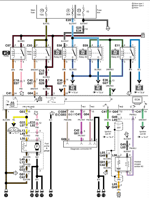
Apollo Wiring Diagram Fuse & Wiring Diagram

Cartel Exit Wand 100 Ft lead 3 wire for use with

How To Connect Your CP31003W Exit Wand To Nice Apollo

Wiring ES Deluxe Exit Wand to Apollo 635/636 & 835/836

Gate Opener Exit Loop Gate Opener
Car Sensor Exit Wand For Gate Opener Ew01 Buy Exit Wand

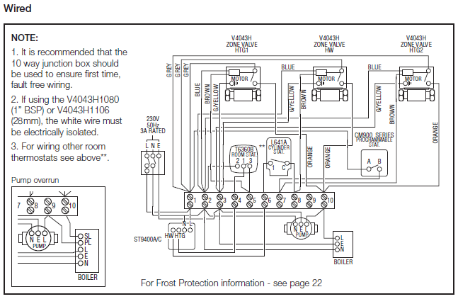
Pin by Amy Zimmerman on NCIDQ Fire protection system

Gate Opener Exit Loop Gate Opener

Loop Detector Wiring Diagram 6
Gate Opener Exit Loop Gate Opener
Gate Opener Exit Loop Gate Opener

Jayco Esc Wiring Diagram How To Connect Your CP31003W
Liftmaster La412u Wiring Diagram Exit Wand Diagram
Liftmaster La412u Wiring Diagram Exit Wand Diagram
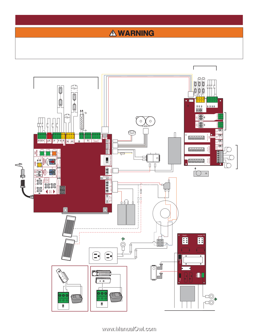
WIRING DIAGRAM, DISCONNECT power AC or solar and battery

Swing Gate Wiring Diagram Complete Wiring Schemas
Liftmaster La412u Wiring Diagram Exit Wand Diagram

Gate Opener Exit Loop Gate Opener